-
E-mail
851012694@qq.com
-
Phone
13916683657
-
Address
No. 9 Kesheng Road, Zhongshan Science and Technology Park, Jiangbei New District, Nanjing City
Nanjing Haizhizhou Heating and Cooling Equipment Co., Ltd
Principle, fault diagnosis and maintenance process of electronic expansion valve
Date: 2025-11-02Read: 4
Electronic expansion valve asThe core throttling components in variable frequency air conditioning and heat pump systems, due to their advantages of fast response speed, high regulation accuracy, and wide adaptability to working conditions, this article aims to systematically introduce the basic structure and working principle of electronic expansion valves, and combine practical cases to analyze in detail their common fault types and scientific diagnosis processes, providing practical technical references for frontline maintenance personnel.
1、 Overview of Electronic Expansion Valve
1.1 Definition and Function
Electronic expansion valve is a throttling device that uses an electronic controller (usually integrated into an air conditioning motherboard) to emit pulse signals, drive stepper motors or electromagnetic coils to precisely adjust the valve needle opening, change the valve port flow area, and achieve automatic control of refrigerant flow.
It plays three key roles in the refrigeration cycle:
Throttling and pressure reduction: converting high-pressure liquid refrigerant into low-pressure wet vapor;
Flow regulation: dynamically adjust the liquid supply based on changes in evaporator load;
Overheating control: Combined with temperature sensors to achieve closed-loop control, ensuring full utilization of the evaporator and preventing liquid hammer.
1.2 Structural composition
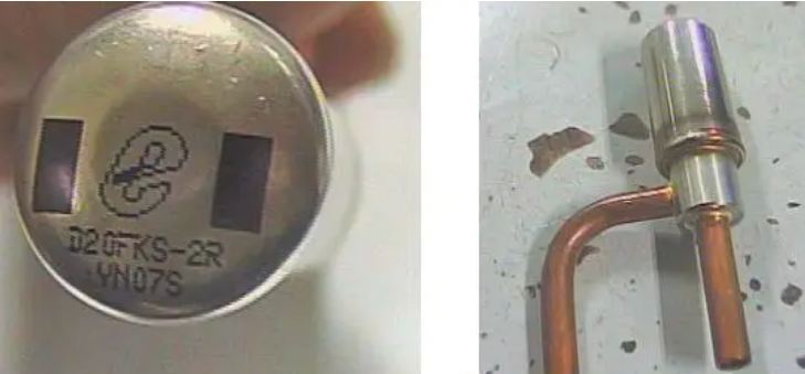
A typical stepper motor electronic expansion valve mainly consists of the following parts:
Valve body components: including valve seat, valve needle, valve core, etc., responsible for opening and closing the refrigerant passage;
Coil component (actuator): receives electrical signals from the control board and drives the internal rotor to rotate;
Transmission mechanism: converts the rotational motion of the motor into the linear lifting of the valve needle;
Connecting terminals and wires: used for communication and power supply with the main control board.
1.3 Control mode
Electronic expansion valves are often driven by pulse width modulation (PWM) or stepper motors. The controller calculates the required opening degree based on parameters such as evaporator outlet superheat, suction pressure, indoor and outdoor temperature difference, and sends pulse signals at a certain frequency to control the opening and closing degree of the valve, achieving a minimum of "one step" (about 1/100 full stroke) fine adjustment.
2、 Analysis of Fault Phenomena and Causes
Fault 1: Electronic expansion valve stuck
Cause: After long-term operation, impurities deposit, oxides accumulate, or lubrication fails, resulting in obstruction of valve needle movement.
Impact: The valve is fixed at a certain opening, losing its regulating ability, and the system cannot adapt to load changes.
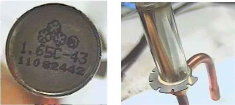
Fault 2: Electronic expansion valve coil detachment
Cause: Improper installation, loose vibration, or external force pulling causing the coil to detach from the valve body.
Impact: Without driving power, the valve cannot operate.
Fault 3: Damaged coil of electronic expansion valve
Causes: overvoltage breakdown, wet short circuit, aging open circuit, etc.
Impact: The coil loses its electromagnetic function and cannot generate driving torque.
Fault 4: Loose wiring of electronic expansion valve
Cause: The plug is not tightly inserted, the terminal is oxidized, and the wire is broken.
Impact: Signal or power interruption, control failure.
Fault 5: Improper installation of electronic expansion valve coil
Cause: Failure to assemble during assemblyPush in place, there is a gap.
Impact: Incomplete magnetic circuit, decreased driving efficiency, and even inability to operate.
Fault 6: Leakage of electronic expansion valve body
Causes: Material defects, mechanical stress concentration, frost cracking, or manufacturing defects.
Impact: The refrigerant seeps out from the valve body and is difficult to repair, requiring a complete replacement.
Fault 7: Welding leakage of electronic expansion valve body
Cause: Poor welding process, virtual welding, sand holes or thermal stress cracking.
Impact: The refrigerant slowly leaks from the weld seam, which is difficult to detect in the initial stage and is often detected through pressure holding leak detection.
3、 Fault diagnosis method and maintenance process
To accurately identify the source of the fault, it is recommended to follow the principle of "external first, internal second, electrical first, mechanical second" for troubleshooting.
Auditory and tactile examination
When starting up and running, listen closely to the valve body for a "click, click" step sound;
Is there any slight vibration in the hand feel, indicating that the coil is working.
Confirm installation status
Check if the coil isInsert the valve body (there should be a "click" locking sensation);
Check if the connector is securely inserted into the motherboard interface;
Verify the correct polarity connection of the wires (refer to the wiring diagram).
voltage test
Use a multimeter to measure the input voltage of the coil, which should normally be within the range of DC 12V ± 1.2V.
resistance detection
Measure the resistance value of each phase winding to the common terminal (usually blue or gray line) in a power-off state, with a standard value of 46 Ω± 3 Ω.
If the resistance is infinite → open circuit (coil broken);
If the resistance is too low or zero → short circuit (coil damage);
If the resistance is normal but the valve does not operate, it is determined that the valve body is stuck.
If the coil is intact, the power supply is normal, and the installation is correct but still does not work, it can be basically determined as mechanical jamming and the valve body needs to be replaced.Attention: The coil resistance of electronic expansion valves of different brands and models may vary slightly. Please refer to the product manual to confirm the standard value.
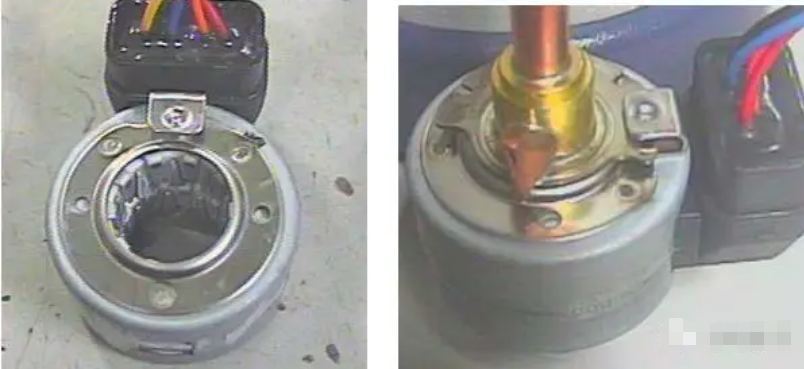
Coil detachment - visual inspection method
Visually inspect whether the coil has slipped off the valve body;
Reinstall and power on to verify if everything returns to normal;
If restored, it is determined to be a fault.
Coil damage - resistance measurement method
The method is the same as above, measure the resistance of each phase winding to the common terminal;
Deviation of 46 ± 3 Ω or open circuit → Replace the coil component. Attention: The coil resistance of electronic expansion valves of different brands and models may vary slightly. Please refer to the product manual to confirm the standard value.
Loose wiring - Connection reliability check
Check if the wiring harness plug is inserted;
Shake the connecting part to observe for poor contact;
Use a multimeter to check the continuity of the circuit in the on/off mode.
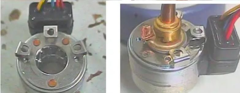
The coil installation is not in place
Check if the bottom of the coil is in contact with the top of the valve body;
Whether there are obvious gaps or tilts;
Reinstall until it is in place.
4、 Preventive measures and maintenance recommendations
To extend the service life of electronic expansion valves and reduce the occurrence of malfunctions, it is recommended to take the following measures:
1. Clean the pipeline before installation: Ensure that there are no impurities such as welding slag, oxide scale, moisture, etc. inside the refrigeration system to avoid clogging or corrosion of the valve core.
2. Standardized welding operation: During welding, the valve body should be protected by cooling (such as wrapping with a damp cloth) to prevent high temperature damage to the internal structure.
3. Regular maintenance: Clean and dry the old units to maintain the purity of the refrigerant.
4. Avoid frequent start stop: reduce the impact of current surge on the coil.
As the core component for precise energy regulation in modern air conditioning systems, the stable operation of electronic expansion valves is directly related to the overall energy efficiency and user experience. Faced with increasingly complex fault scenarios, maintenance personnel not only need to have a solid theoretical foundation, but also need to master scientific detection processes and tool usage skills.
*Note: The resistance value (46 ± 3 Ω) and voltage value (12 ± 1.2V) mentioned in the article are example data from a mainstream brand. Please refer to the technical information provided by the equipment manufacturer for specific parameters.