-
E-mail
sjzhangtian@163.com
-
Phone
137-2278-0778
-
Address
12-1-502 Rongguo Garden, No. 528 Zhongshan East Road, Chang'an District, Shijiazhuang City
Product Categories
Shijiazhuang Aerospace Automation Technology Co., Ltd
NHR-7400/7400R series LCD four-way PID regulator/recorder
NegotiableUpdate on 08/04
- Model
- Nature of the Manufacturer
- Producers
- Product Category
- Place of Origin
Overview
Overview: The NHR-7400/7400R series LCD four-way PID regulator/recorder can switch between fixed-point control and regulation, and program segment control and regulation according to production control requirements. Adopting artificial intelligence PID control algorithm and four-way independent PID regulation, it has the characteristics of no overshoot or overshoot, and is suitable for control systems that require high-precision measurement. It can control measurement signals such as temperature, pressure, liquid level, and speed. According to the control method, it can be divided into the following categories: NHR-7410/7410R four-way PID regulator/recorder can input four measurement signals, which are compared with the set control target value and output four independent control signals based on the PID operation results. Control output methods such as voltage, current, SSR drive, single/three-phase thyristor zero crossing trigger can be selected. The NHR-7440/7440R four channel program regulator/recorder can input four measurement signals and set target curves for control according to the requirements of the production process. It can achieve the operation of running, stepping, pausing, ending, and waiting states for curve control. Instrument panel 160 * 80mm (Type A) 80 * 160mm (Type B) 96 * 96mm (Type C) ① Display panel
Product Details
overview
The NHR-7400/7400R series LCD four-way PID regulator/recorder can switch between fixed-point control and regulation, and program segment control and regulation according to production control requirements. Adopting artificial intelligence PID control algorithm and four-way independent PID regulation, it has the characteristics of no overshoot or overshoot, and is suitable for control systems that require high-precision measurement. It can control measurement signals such as temperature, pressure, liquid level, and speed.
![]() According to the control method, it can be divided into the following categories:
According to the control method, it can be divided into the following categories:
| NHR-7410/7410R Four way PID regulator/recorder |
It can input four measurement signals, which are compared with the set control target value and output four independent control signals based on PID calculation results. It can choose control output methods such as voltage, current, SSR drive, single/three-phase thyristor zero crossing trigger, etc. |
| NHR-7440/7440R Four channel program regulator/recorder |
Four measurement signals can be input, and the target curve can be set for control according to the requirements of the production process. It can achieve the operation of running, stepping, pausing, ending, and waiting states for curve control. |
 instrument panel

|

|

|
| 160 * 80mm (Type A) | 80 * 160mm (Type B) | 96 * 96mm (Type C) |

|
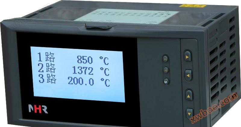
① Display panel ② USB and SD interfaces ③ Confirm button  Display channel switch key  Time scale switch, manual/automatic switch key  ④ Right cursor shift key ⑤ Left cursor shift key ⑥ Cursor up key ⑦ Cursor down key |
|
Simple visual indication

|
 Wiring diagram

| Note 1: If different functions are marked on the same group of terminals in the wiring diagram, only one function can be selected. If RS485 and RS232 are connected to the same set of terminals, only one can be selected. Note 2: The direction of the wiring terminals on the back cover of the horizontal and vertical instruments is different, as shown in Figure 1. |
|
 instrument selectionNHR-74 □-□-□-□-□-□
Four way PID regulator ①②③③③⑤⑥
NHR-74 □R-□-□-□-□-□
Four channel PID control recorder ①②③③③⑤⑥
| ① Control method | ② Specification and size | ||
| code | control mode | code | Width * Height * Depth |
|
10 40 |
Fixed-point PID control Program segment control |
A B C |
160 * 80 * 110mm (horizontal) 80 * 160 * 110mm (vertical) 96 * 96 * 110mm (Method) |
| ③ Control output (Note 1) | ④ Alarm output | ||
| code | Output type (load resistance RL) | code | Alarm channel (relay contact output) |
|
0 1 2 3 4 5 K1 K3 K4 K5 |
4-20mA(RL≤600Ω) 1-5V(RL≥250KΩ) 0-10mA(RL≤1.2KΩ) 0-5V(RL≥250KΩ) 0-20mA(RL≤600Ω) 0-10V(RL≥4KΩ) RELAY CONTACT OUTPUT Zero crossing trigger pulse output of thyristor Solid state relay driving voltage output Phase shifted trigger output |
X 1 2 |
no-output 1-limit alarm 2-limit alarm |
| ⑤ Power supply | |||
| code | Voltage range | ||
| A D |
AC/DC 100~240V(AC/50-60Hz) DC 20~29V |
||
| ⑥ Additional functions (all of the following functions can be selected, separated by "/", functions that are not selected can be omitted) | |||
| Communication output | Feed output | ||
| code | Communication interface (communication protocol) | code | Feed output (output voltage) |
| D1 D2 D3 |
RS-485 communication interface (Modbus RTU) RS232 communication interface (Modbus RTU) RS232C printing interface |
1P 2P |
1-channel feeding output 2-channel feeding output |
| Suitable for instruments with records | |||
| USB transfer function | Extended functionality | ||
| code | Transfer function | code | Extended functionality |
| U | USB card transfer (with 1GB USB flash drive) | SD | SD card expansion (capacity 8GB) |
1. When the control output methods of each channel are inconsistent, please provide an explanation in the selection section.
2. Example of instrument model:
Example 1: NHR-7410-A-0-2-A-D1/1P (four PT100 inputs, two 4-20mA transmission outputs)
Meaning: Four channel fixed-point PID control, specifications of 160 * 80 * 110mm, 4-20mA control output, 2-limit alarm output, AC100-240V power supply, RS485 communication, 1-channel power supply output.
Example 2: NHR-7440R-B-3-2-A-2P/SD (four 4-20mA inputs, four 0-5V control outputs).
Meaning: Four channel program segment control with recording function, specifications of 80 * 160 * 110mm, 0-5V control output, 2-limit alarm output, AC100-240V power supply, 2-channel power supply output, SD card expansion function.
| signal type | Range of measurement | signal type | Range of measurement |
| B S K E T J R N F2 Wre3-25 Wre5-26 Cu50 Cu53 Cu100 Pt100 BA1 |
400~1800℃ -50~1600℃ -100~1300℃ -100~1000℃ -100.0~400.0℃ -100~1200℃ -50~1600℃ -100~1300℃ 700~2000℃ 0~2300℃ 0~2300℃ -50.0~150.0℃ -50.0~150.0℃ -50.0~150.0℃ -200.0~650.0℃ -200.0~600.0℃ |
BA2 0~400Ω 0~350Ω 30~350Ω 0~20mV 0~100mV 0~20mA 0~10mA 4~20mA 0~5V 1~5V 0~10V 0-10mA square root 4-20mA square meter 0-5V square root 1-5V square root |
-200.0~600.0℃ -9999~99999 Special customization Special customization -9999~99999 -9999~99999 -9999~99999 -9999~99999 -9999~99999 -9999~99999 -9999~99999 Special customization -9999~99999 -9999~99999 -9999~99999 -9999~99999 |
| signal type | 4-20mA | 1-5V | 0-10mA | 0-5V | 0-20mA | 0-10V (specially customized) |
| Load resistance RL | RL≤600Ω | RL≥250KΩ | RL≤1.2KΩ | RL≥250KΩ | RL≤600Ω | RL≥4KΩ |
Similar Product Recommend


