-
E-mail
1702662999@qq.com
-
Phone
18915186518
-
Address
No. 99 Tongtai Avenue, Industrial Concentration Zone, Jinhu County, Jiangsu Province
Product Categories
Jiangsu Huayun Instrument Co., Ltd
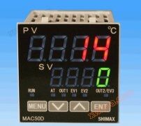
PID intelligent temperature controller | Manufacturer price | Specification selection
NegotiableUpdate on 07/07
- Model
- Nature of the Manufacturer
- Producers
- Product Category
- Place of Origin
Overview
Manufacturer's price: starting from 39.00 55.00 1254.00, batch size: 1 unit, 1 unit, 1 unit. Specification selection: Processing customization is brand HY/Huayun model KZ810, control type, temperature control mode, intelligent temperature control regulator, measuring object thermocouple, thermal resistance temperature range 0-400 (℃), temperature measurement error 0.5 (℃), opening size 45 * 45, also available in 68 * 68 and other (mm) installation types. There are various embedded output signals to choose from, relay output (mA), working voltage 220 (V), external size 48 * 48 (mm), weight about 230 (Kg)
Product Details
Manufacturer's price:
| price | ¥ 39.00 | ¥ 55.00 | ¥ 1254.00 |
| Starting from batch | ≥1 tower | ≥1 tower | ≥1 tower |
| Customized processing | correct | brand | HY/Huayun | ||
| model | KZ810 | control type | temperature | control model | Intelligent temperature control regulator |
| Measurement Object | Thermocouple, Thermistor | temperature range | 0-400(℃) | temperature measurement error | 0.5(℃) |
| Dimension | 45 * 45, also available in 68 * 68 sizes (mm) | Installation type | Embedded | output signal | Multiple options, relay output (mA) |
| working voltage | 220(V) | External dimensions | 48*48(mm) | weight | About 230 (Kg) |

1. PID debugging steps
There is no control algorithm more effective and convenient than PID regulation law. Some trendy regulators nowadays are mostly derived from PID. It can even be said that PID regulators are the mother of other control and regulation algorithms.
Why is PID widely used and long-lasting?
Because PID solves the fundamental problems that automatic control theory needs to address, namely system stability, speed, and accuracy. By adjusting the parameters of the PID controller, it is possible to balance the system's load capacity and disturbance resistance while maintaining stability. Additionally, by introducing an integral term into the PID controller, a zero integration point is added to the system, making it a first-order or higher-order system. This ensures that the steady-state error of the system's step response is zero.
Due to the vast differences in the controlled objects of automatic control systems, the parameters of PID must also vary accordingly to meet the performance requirements of the system. This brings considerable trouble to users, especially beginners. Here are some general steps for debugging PID parameters:
1. Negative feedback
Automatic control theory is also known as negative feedback control theory. Firstly, check the system wiring to ensure that the feedback is negative. For example, in a motor speed control system, if the input signal is positive and the motor is required to rotate forward, the feedback signal should also be positive (in PID algorithm, error=input feedback). At the same time, the higher the motor speed, the greater the feedback signal. The other systems use the same method.
2. General principles for PID debugging
a. Increase the proportional gain P when the output is not oscillating.
b. Reduce the integration time constant Ti when the output is not oscillating.
c. Increase the differential time constant Td when the output is not oscillating.
3. General steps
a. Determine the proportional gain P
When determining the proportional gain P, the first step is to remove the integral and derivative terms of the PID, usually by setting Ti=0 and Td=0 (see PID parameter setting instructions for details), to make the PID purely proportional. Set the input to 60%~70% of the maximum value allowed by the system, gradually increase the proportional gain P from 0 until the system oscillates; Conversely, gradually decrease the proportional gain P from this point until the system oscillation disappears. Record the proportional gain P at this point and set the PID proportional gain P to 60% to 70% of the current value. Proportional gain P debugging completed.
b. Determine the integral time constant Ti
After determining the proportional gain P, set a larger initial value for the integration time constant Ti, gradually decrease Ti until the system oscillates, and then gradually increase Ti in reverse until the system oscillation disappears. Record the current Ti and set the integral time constant Ti of the PID to 150% to 180% of the current value. The integration time constant Ti has been debugged.
c. Determine the integral time constant Td
The integral time constant Td generally does not need to be set, it can be set to 0. To set, the same method as determining P and Ti is used, taking 30% when there is no oscillation.
d. System no-load and on load joint debugging, and then fine tune the PID parameters until they meet the requirements.
Similar Product Recommend


