-
E-mail
1702662999@qq.com
-
Phone
18915186518
-
Address
No. 99 Tongtai Avenue, Industrial Concentration Zone, Jinhu County, Jiangsu Province
Product Categories
Jiangsu Huayun Instrument Co., Ltd

Sewage level gauge
NegotiableUpdate on 03/21
- Model
- Nature of the Manufacturer
- Producers
- Product Category
- Place of Origin
Overview
Overview of Sewage Tank Level Gauge Products
Product Details
Overview of Sewage Tank Level Gauge Products
The sewage tank level gauge is based on the traditional RF capacitor level and adds a more powerful circuit design. This design adds digital processing technology to the analog signal, which eliminates radio frequency interference.
The sewage tank level gauge overcomes the problems of leakage and disconnection that traditional mechanical level gauges are prone to, and also overcomes some non-contact clutter interference. Specially suitable for measurement in environments with high temperature, strong corrosion, strong adhesion, high pressure, and vacuum.
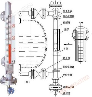
The UHZ series sewage level gauge is mainly used in various storage tanks, separation tanks, reaction tanks, fermentation tanks, oil products, liquefied gas, strong acid and alkali liquids, weak acid and alkali liquids, power plant boiler steam drums, deaerators, drainage tanks, return tanks, high and low pressure heaters, condensers, evaporators and other pressure vessels in the petroleum, chemical, refining, pharmaceutical, food, wine, beverage and other industries, as well as 1Cr18Ni9Ti, 316L. Liquid level measurement and display of 1Cr18Ni9Ti+PTFE (lined with polytetrafluoroethylene) and PVC plastic compatible media, multi-point liquid level switch output, and electric remote transmission (4-20mA, 0-10mA DC) output. The installation forms include standard type, top mounted type, float level gauge, insulation type, frost proof type, etc. for you to choose from. The working principle and basic structure of UHZ series sewage level gauge are based on buoyancy and magnetic principles. It uses the magnetic float inside the measuring cylinder to rise or fall with the measured liquid level, and through the attraction of the magnetic field, the dual color flip column on the external display of the measuring cylinder flips to achieve the purpose of displaying the position of the measured liquid level. The sewage level gauge uses red to indicate the liquid part, white to indicate the no liquid or vapor part, or white to indicate the liquid part and red to indicate the no liquid or vapor part.

Manufacturer's price:
Specification parameters:
The UHZ series sewage level gauge is mainly used in various storage tanks, separation tanks, reaction tanks, fermentation tanks, oil products, liquefied gas, strong acid and alkali liquids, weak acid and alkali liquids, power plant boiler steam drums, deaerators, drainage tanks, return tanks, high and low pressure heaters, condensers, evaporators and other pressure vessels in the petroleum, chemical, refining, pharmaceutical, food, wine, beverage and other industries, as well as 1Cr18Ni9Ti, 316L. Liquid level measurement and display of 1Cr18Ni9Ti+PTFE (lined with polytetrafluoroethylene) and PVC plastic compatible media, multi-point liquid level switch output, and electric remote transmission (4-20mA, 0-10mA DC) output. The installation forms include standard type, top mounted type, float level gauge, insulation type, frost proof type, etc. for you to choose from. The working principle and basic structure of UHZ series sewage level gauge are based on buoyancy and magnetic principles. It uses the magnetic float inside the measuring cylinder to rise or fall with the measured liquid level, and through the attraction of the magnetic field, the dual color flip column on the external display of the measuring cylinder flips to achieve the purpose of displaying the position of the measured liquid level. The sewage level gauge uses red to indicate the liquid part, white to indicate the no liquid or vapor part, or white to indicate the liquid part and red to indicate the no liquid or vapor part.
Manufacturer's price:
| price | ¥ 400.00~49800.00 yuan |
| Starting from batch | ≥1 tower |
Specification parameters:
| Customized processing | deny | brand | Vauen | model | LMK 458H |
| type | Input type liquid level transmitter | measuring range | 0-200mH20 | measurement accuracy | 0.1%FSO |
| material | stainless steel | power supply | 0-20mA | output signal | 20(mA) |
| Measurement medium | Sewage sludge | Is it a cross-border source of goods | deny | resolution | 0.001 |
Working principle of sewage tank level gauge:
An extension bypass pipe is installed on the outside of the bucket, and a liquid level indicator is installed outside the bypass pipe. A floating ball with a magnet is placed inside the bypass pipe. As the magnetic color plate contains a magnet with opposite magnetic properties to the floating ball, it will attract the magnetic color plate to flip when it rises. The color of the magnetic color plate will change from white to red (or silver to gold) to indicate the actual liquid level height.

Structure and principle of sewage level gauge
1. Basic type:
According to the principle of buoyancy, the float moves up and down in the measuring tube with the rise and fall of the liquid level. The magnetic steel inside the float drives the red and white flip columns to flip 180 ° through coupling. When the liquid level rises, the flip column changes from white to red, and when it falls, it changes from red to white, thus achieving liquid level indication.
2. Electric remote transmission:
Install a transmitter on the float level gauge, move the float up and down, and use magnetic coupling to sequentially move the measuring elements inside the guide rod to obtain resistance signal changes, convert them into standard signal outputs of 0-10mA or 4-20mA, and connect them with display instruments or computers to achieve remote transmission.
3. Upper and lower limit switch output:
A controller is installed on the liquid level gauge riser at the upper and lower limit positions set by the user. The controller is equipped with a self holding reed switch, which uses a magnetic float to move with the liquid level to trigger an alarm or limit control when the reed switch is activated.
System composition and wiring
1. Upper and lower limit switch output:
Composed of a self retaining reed switch and converter, the reed switch and converter are installed on site and in the control room respectively, with three pairs of contact switches provided by the converter.
2. Electric remote transmission:
It consists of two parts: the measuring unit and the transmitting unit.
3. Intrinsic safety explosion-proof:
A with intrinsic safety explosion-proof, upper and lower limit switch output type
The explosion-proof switch consists of a reed switch and a safety barrier with relay contacts, which can directly provide users with a pair of normally open or normally closed contacts. If users require more touchpoints, they can place special design orders.
B-belt security explosive remote transmission type
Suitable for use in π - class electrical equipment (factory use), C-class gas, * * * high surface temperature group T4 (135 ℃).
C Precautions for use
① The transmitter housing is equipped with an external grounding, which must be reliably grounded when used by the user.
② The use of safety barriers should comply with the relevant instructions.
③ The connecting cable between the transmitter and the intrinsic safety end of the safety barrier is a two core shielded cable with a core wire cross-sectional area greater than 0.5m, and the cable allows a distributed capacitance of 0.8 μ F
1. Suitable for high temperature, high pressure, strong acid, strong alkali and explosion-proof requirements, with a simple structure, reliable and durable, and can be equipped with various optional accessories to make control easier.
2. Install a liquid level transmitter and magnetic switch, which can be installed or adjusted at any time without stopping the machine.
3. If the power supply is interrupted, the on-site magnetic switch is not affected and has high accuracy.
4. Add a color swatch of a different color every 10 centimeters to make the liquid level easy to identify.
5. Used for dyeing and finishing equipment, wastewater treatment, power plants, chemical equipment, hot kerosene boilers, and petrochemical industry, etc

Top Ten Technical Advantages of Sewage Tank Level Gauge
1) Strong adaptability: It can work reliably in environments with high temperature, strong corrosion, and heavy dust.
Medium temperature -200~+230 ℃ (customized beyond this range)
2) Unique header three button design, easy to operate.
By using CPU processing technology, the different principles of RF capacitance, RF admittance, and RF inductance can be applied to various complex media and harsh working conditions.
3) No maintenance required: The sensor is sturdy and durable, with no moving parts, so there is no need for maintenance once it is put into operation.
4) Widely used: high temperature, ultra-low temperature, high pressure, vacuum, liquid, solid, powder, particle
5) Complete open functionality: It can be seamlessly connected to various recorders, PLCs, DCS, and other control systems.
6) Any zero point: The zero point can be specified arbitrarily within the length range of the sensor, indicating where to point and where to mark.
7) Strong mode menu: Up to 20 calibration segments can be performed to achieve higher accuracy (intelligent accuracy up to 0.25%).
8) The structure can be customized and the installation is flexible: according to the on-site working conditions, users can customize various installation structures:
Single pole, parallel double pole, concentric shaft, light cable, heavy cable.
9) Output: 4-20mA RS485、 Dry contact point, pointer head, digital display head
10) Compared to traditional capacitive level meters, the VIVO2020 series RF level meter adds a more powerful circuit design to the traditional RF level meter, which can accurately measure small changes in level and fundamentally eliminate the RF interference components superimposed in the DC 4-20mA output of the traditional RF level meter, ensuring ultra stability of measurement and output signals. Due to the use of radio frequency technology and microcomputer technology, the problems of large temperature drift, difficult calibration, and fear of adhesion in traditional point type level gauges have been solved, overcoming the problems of leakage, disconnection, and other issues that traditional mechanical level gauges are prone to. It can be widely used for various liquid and solid level alarms (switch type does not require a secondary meter, the body can have two alarm points) and joint control. Especially in environments with high temperature, strong corrosion, strong viscosity, and heavy dust, it is incomparable to other types of level gauges.Technical parameters of sewage tank level gauge
|
Supply Voltage |
24VDC,100mA |
|
Output |
4-20mA (analog, intelligent) |
|
communication interface |
RS485 |
|
Accuracy |
± 0.5% FS (analog) ± 0.25% FS (intelligent) |
|
Sensitivity |
≤ 0.1PF |
|
Range |
5~50000PF |
|
response time |
5ms (simulation) 1ms (intelligent) |
|
***Large load |
650 Ω (analog) 450 Ω (intelligent) |
|
Overload pressure |
65kg/ cm2@38 ℃,34.5kg/ cm2@232 ℃ |
|
medium temperature |
-40 ℃ to 232 ℃ (declaration required for temperatures greater than 150 ℃) (analog, intelligent); -200~+232 ℃ (customized if exceeding this range) (switch) |
|
ambient temperature |
-20 ℃~75 ℃ (customized for temperatures above 75 ℃) (analog, intelligent); |
|
protection grade |
IP65 |
|
Explosion proof grade |
D Ⅱ BT6 (supply by agreement) |
|
sensor length |
Pole type * * * length 3.66m, cable type * * * length 120m |
|
Sensor material |
316 stainless steel; Ceramics; Teflon |
|
Display header |
0-100% (analog) 4-digit LCD (intelligent) |
|
Installation method |
M33 X 2 thread or flange |
Basic difference of sewage tank level gauge:
Measurement range LD: 200-15000mm
L1: It is related to the specific gravity of the medium and the material of the float, as shown in the table below
|
Medium specific gravity |
L1(mm) |
|
|
Rust proof aluminum float (LF2) Float wrapped in LF2 fluoroplastic |
Stainless steel float (1Cr18ni9Ti) |
|
|
0.45 |
463 |
|
|
0.55 |
286 |
|
|
0.65 |
210 |
|
|
0.75 |
166 |
|
|
0.85 |
140 |
340 |
|
0.95 |
120 |
260 |
|
≤1.0 |
113 |
220 |
D: ¢ 52~¢ 83: ¢ 115~¢ 200 (depending on pressure)
Measurement accuracy: ± 10mm Medium temperature: ≤ 80 ℃, can also be made to ≤ 480 ℃
Medium specific gravity: ≥ 0.4 Medium viscosity: ≤ 0.02Pa·S
Connecting flange:
|
DN20 |
PN(MPa) |
|
|
0.6~2.5 |
4.0~16.0 |
|
|
Standard number |
HG20593-97 |
HG20595-97 |
|
Dg15 |
Pg(Kgf/cm2) |
|
|
220 |
320 |
|
|
Standard number |
H12-0-2 |
H12-0-3 |
Note: HG20595-97 Our factory's sewage tank level gauge uses FM surface. The installation of the level gauge is affected by the environment. If the spatial position L1 is less than 300, it should be clearly stated when placing an order.
The RZ-UDZ-3 remote transmission magnetic float level gauge/B explosion-proof type is composed of five parts: main body, magnetic float, sensor, transmitter, and flap indicator. Its working principle is that the magnetic float inside the main body simultaneously attracts the reed switch at the corresponding position inside the sensor with the rise and fall of the liquid level. Thus, the total resistance (or voltage) inside the sensor changes accordingly, and then the change in resistance (or voltage) is converted into a standard current output of 4-20mA · DC through a transmitter. The XMT series digital liquid level controller specially produced by our factory displays the liquid level and sets upper and lower limit alarms, achieving positional control or adjustment of the liquid level. In addition, it is matched with the XMGA light column digital display regulator produced by our factory, which provides a more intuitive display. Or it can be matched with any other display instrument or regulator that can accept 4-20mA · DC signal input to achieve remote display of liquid level, positional control, intermittent or continuous PID regulation.
Selection Table for Sewage Tank Level Gauge:
Selection Table for Sewage Tank Level Gauge:
|
model |
code |
describe |
|
XT-UHZ |
Sewage tank level gauge |
|
|
Type of liquid level gauge |
1 |
Flip board indicator (local display type) |
|
3 |
Remote transmission with flip board |
|
|
Level gauge model |
0 |
Basic type |
|
W |
Thermal insulation type |
|
|
D |
plug-in type |
|
|
J |
anti-corrosive |
|
|
S |
Frost proof type |
|
|
Z |
Insulated and corrosion-resistant type |
|
|
Y |
Insert corrosion-resistant type |
|
|
alarm control |
0 |
No alarm |
|
1 |
With upper limit |
|
|
2 |
With lower limit |
|
|
3 |
Bring upper and lower limits |
|
|
Float material |
P |
stainless steel |
|
L |
Rust proof aluminum |
|
|
T |
titanium |
|
|
S |
pvc plastic |
|
|
F |
Fluoroplastic wrapping |
|
|
Material |
P |
stainless steel |
|
L |
Rust proof aluminum |
|
|
T |
titanium |
|
|
S |
pvc plastic |
|
|
F |
Fluoroplastic pipe |
|
|
PF |
PTFE lining |
|
|
PP |
Lined with propylene |
|
|
PE |
Lined with ethylene |
|
|
Connecting flange |
See Table 1 |
|
|
medium temperature |
See Table 2 |
|
|
Actual usage pressure |
See Table 3 |
|
|
Medium specific gravity |
Please indicate |
|
|
Order length |
Please indicate |
|
|
/B |
Explosion proof type |
Table 1:
|
nominal pressure |
Mpa |
Kgf/ cm2 |
|||||||||
|
0.6 |
1.0 |
1.6 |
2.5 |
4.0 |
6.3 |
10 |
16 |
220 |
320 |
||
|
code |
stainless steel |
A |
B |
C |
D |
E |
F |
G |
H |
I |
J |
|
carbon steel |
a |
b |
C |
d |
e |
f |
g |
h |
i |
j |
|
|
Flange standard |
HG20593-97 DN20(RF) |
HG20595-97(RF)DN20 |
H12-0-2 |
H12-0-3 |
|||||||
Table 2
|
medium temperature |
-40~0℃ |
≤80℃ |
≤100℃ |
≤150℃ |
≤300℃ |
≤350℃ |
≤480℃ |
|
code |
A |
B |
C |
D |
E |
F |
G |
Table 3:
|
Use pressure (Actual) |
Mpa |
Kgf/ cm2 |
||||||||
|
0.6 |
1.0 |
1.6 |
2.5 |
4.0 |
6.3 |
10 |
16 |
220 |
320 |
|
|
code |
A |
B |
C |
D |
E |
F |
G |
H |
I |
J |
Installation and maintenance of sewage tank level gauge
1. The installation of the liquid level gauge must be vertical to ensure that the float component can move freely up and down inside the main pipe.
2. Magnetic conductors are not allowed to approach the main body of the liquid level gauge, otherwise it will directly affect the correct operation of the liquid level gauge.
3. After the installation of the liquid level gauge is completed, it needs to be calibrated with magnetic steel to guide the flip column once, so that the display below the zero position is red and the display above the zero position is white.
4. When the liquid level gauge is put into operation, the valve of the lower drainage pipe should be opened first to allow the liquid medium to enter the main pipe smoothly, avoiding the liquid medium from rushing with the floating ball component
Rapid ascent leads to malfunction and disorderly flipping of the flipping column. If this phenomenon occurs, it can be recalibrated with magnetic steel after the liquid level stabilizes.
Application instructions for sewage level gauge
l、 Install a shut-off valve between the side mounted level gauge and the upper and lower distribution pipes of the tested container to open or close the level gauge; On the other hand, it brings convenience to the maintenance of liquid level gauges. When the upper and lower shut-off valves are closed, the bottom drain flange of the level gauge can be opened or the drain screw can be removed, and the main body of the level gauge can be cleaned by injecting clean water.
2. When installing a level gauge, the perpendicularity of the flange centerline should be ≤ 4 ‰. When the measurement range of the level gauge is greater than 3 meters, it is necessary to consider adding a reinforced flange (or spider) in the middle as a fixed support to increase strength.
3. The isolation line between the remote liquid level transmitter and the secondary instrument should have a core wire cross-sectional area greater than 0.8mm When laying parallel to the AC power supply, a distance of at least 20 centimeters should be maintained. It is recommended to lay it separately through iron pipes or with shielded two core cables. The shielding layer can only be grounded at one end.
4. The liquid level controller is selected, and its contact capacity is designed for resistive loads. If non resistive or high-power loads are used, intermediate relays should be used for conversion.
5. It is not advisable to use this level gauge for situations where there are suspended impurities in the liquid medium and magnetic substances, as these impurities can cause blockage in the float component.
6. The blind spot (L1) in the external structure is related to the density of the medium. Therefore, different media have different blind spots.
Similar Product Recommend