-
E-mail
shouwang6368@126.com
-
Phone
18051034886
-
Address
No. 19, Tuanshan East Road, Lishui Economic Development Zone, Nanjing City
Product Categories
Nanjing Shouwang Machinery Equipment Co., Ltd


Powder conveyor
NegotiableUpdate on 01/05
- Model
- Nature of the Manufacturer
- Producers
- Product Category
- Place of Origin
Overview
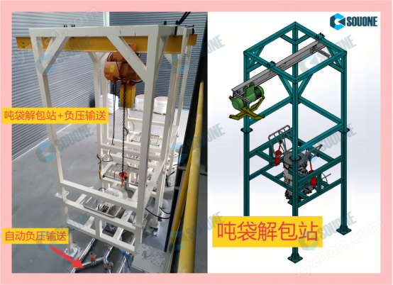
The working principle of the powder conveyor: When the fan extracts air from the powder collection tank, a strong negative pressure is generated inside the tank. The powder in the powder bag is sucked into the powder collection tank along with the air through the powder suction pipe. The filter inside the powder collection tank will effectively prevent dust and small particles from being extracted with the air.
Product Details
Powder conveyorThe working principle of
When the fan extracts air from the powder collection tank, a strong negative pressure is generated inside the tank. The powder in the powder bag is sucked into the powder collection tank along with the air through the powder suction pipe. The filter inside the powder collection tank will effectively prevent dust and small particles from being extracted with the air; In this process, the pressure storage tank next to the powder collection tank is filled with a certain pressure of air. When the suction is completed, the air in the pressure storage tank will be released in an instant pulse, blowing back the filter and removing the material adsorbed on the filter element, so that the filter element can maintain its normal filtration area without affecting production.
When the system starts running, the unloader below the powder collection tank starts working, and the central feeding system continuously drops the powder material. In order to prevent the accumulation of powder in the tank and prevent it from falling easily, a high-frequency oscillator is installed below the tank to ensure smooth powder dropping; If the powder conveying capacity is not high, an intermittent feeding method can be used, using gas jet to form negative pressure. When the powder bucket is filled with material, the suction is automatically stopped through the level control of the level gauge, and the back blowing air port is opened. The pneumatic discharge valve is opened to discharge the material, and then controlled by the level gauge at the lower end of the discharge port. When the level is lower than the level, the discharge valve is closed and the suction resumes. The above continuous or intermittent feeding processes can be set and automatically controlled by PLC.
Powder conveyor is a system that achieves the purpose of powder transportation through vacuum suction, combined with comprehensive factors such as filtration, blowback, discharge, and valve body control. The system is mainly used for conveying materials such as powdered materials, granular materials, and mixtures of powdered and granular materials; The system can automatically transport various materials to the hoppers of packaging machines, injection molding machines, crushers and other equipment, and can also directly transport mixed materials to mixers and various mixing reaction tanks, solving the problem of dust during feeding and reducing the labor intensity of workers. It is the preferred system for powder conveying.

Description of the control program for the operation of the feeding machine
(1) Input I1 to close (power on)
First, open the discharge valve Q3 of the feeding machine and delay before proceeding to the next step;
(2) Pneumatic feeding program: B001TH/TL cycle timing alternating switching (suction and discharge switching)
Material suction action:
Suction time=feeding time+emptying time;
During the TH timing period: both feed Q1 and suction Q2 are turned on simultaneously. B004 delays until feed Q1 is disconnected, and Q4 (clear) flashes continuously until suction Q2 stops. B001TH suction timing time is up, switch to discharge.
Material release action:
During TL timing: Switch to the discharge Q3 opening, while Q4 (reverse blowing) flashes and vibrates.
BOO1TL feeding timer time up, switch to suction
(3) Input I1 disconnected (stopped)
Immediately trigger the discharge valve to discharge the material (while blowing back the filter element), and stop the machine after a delay.
When the device is configured with high and low level sensors, the device runs according to the following program:
(4) When the high material level triggers the action, the discharge valve is immediately triggered to discharge the material, and after a delay, the standby stops.
(5) When the low material level action is triggered, execute the second running program
Attention: Incorrect parameter time setting can cause blockage or insufficient conveying capacity of the vacuum feeder, and in severe cases, even damage the vacuum feeder
Please adjust the parameters under the guidance of professional personnel or call the manufacturer for technical support.
Specific parameters:
|
Project/Model |
SWP180 type
|
SWP250 type
|
SWP320 type |
SWP430 type
| SWP560 type |
SWP800 type | |
| compressed air | pressure | 0.5-0.8Mpa | 0.5-0.8Mpa | 0.5-0.8Mpa | 0.5-0.8Mpa | 0.5-0.8Mpa | 0.5-0.8Mpa |
| pressure | air consumption
| 0.36M3/min | 0.65M3/min | 1.26M3/min | 2.7M3/min | 3.6M3/min | 4.5M3/min |
| conveying capacity | 0.1-0.5T/h | 0.3-0.8T/h | 0.5-1.2T/h | 1.3-3.5T/h | 2.5-6.0T/h | 5.0-10.0T/h | |
| filter | Ti07 German imported filter element, PTFE filter element, Ti sintered filter element | ||||||
| filtration area |
0.33M2 |
0.33M2 | 0.99M2 |
2M2 |
2.3M2 | 3.3M2 | |
| Suction port | DN38 |
DN50 |
DN75 | DN100 |
DN100 | DN150 | |
| Cutting diameter | φ150 | φ150 | φ200 | φ200 | φ250 |
φ300 | |
| Vacuum silo volume | 7L | 18L | 35L | 56L |
96L | 250L | |

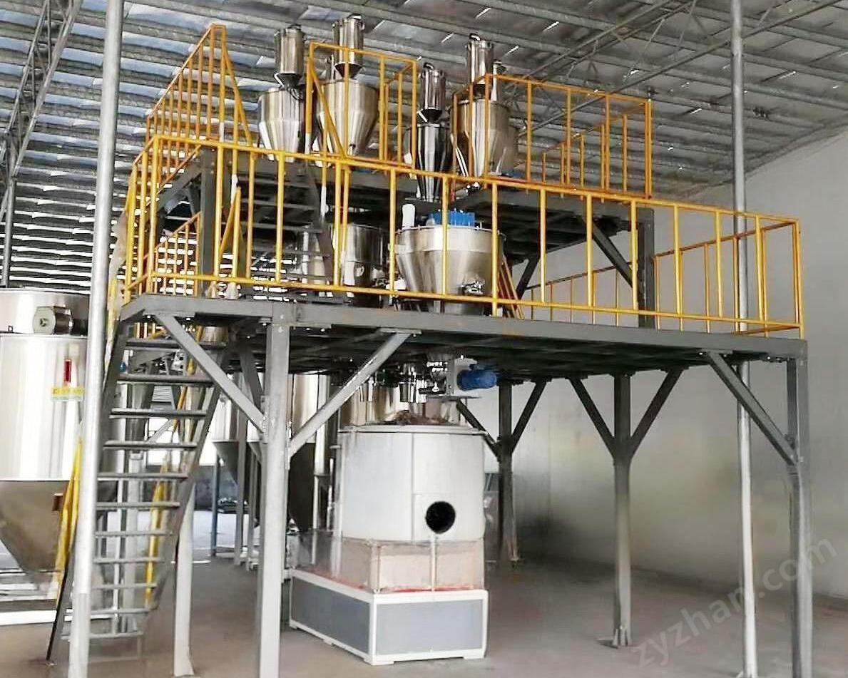
Powder conveyorDetailed explanation of installation, working process, and maintenance matters
1、 Installation process and precautions
Basic preparation and marking
Before installation, it is necessary to complete the civil engineering works such as the transfer tower and silo, and check whether the position of the anchor bolts and embedded steel plates meets the design requirements.
Define the centerline of the equipment to ensure accurate installation positions of the racks (head rack, middle rack, tail rack) and avoid subsequent conveyor belt deviation.
Equipment assembly steps
Rack installation: Install the head frame, middle frame, and tail frame in order to ensure levelness and verticality.
Installation of idler and drum: Install the lower idler and reversing drum, place the conveyor belt on the lower idler, and then install the upper idler.
Installation of drive device: Install the transmission drum and drive device (motor, reducer), paying attention to the concentricity of the motor axis and reducer axis, and the radial displacement of the coupling should be ≤ 0.5mm
Conveyor belt connection: Use vulcanization or mechanical joint method to connect the conveyor belt. During vulcanization, the pressure is controlled at 5-10Kg/cm ², the temperature is around 140 ℃, and the insulation time is calculated according to the formula (such as 16+(layers -3) x 2 minutes).
Installation of auxiliary components: Install tensioning device, cleaner, guide groove, cover, etc., to ensure that the cleaner is in close contact with the conveyor belt and the guide groove is well sealed.
Key points for installation and debugging
No load and load test run: The new equipment needs to run for 2 hours without load and 8 hours with load, checking the direction of drum rotation, electrical signals, brake clearance, etc.
Deviation adjustment: If the conveyor belt deviates, adjust the tail to change direction to the drum or spiral tensioning device; Local deviation can be automatically corrected using a self-aligning roller.
Safety protection: When a pedestrian walkway is installed behind the tail drum, railings or protective covers must be installed; A protective shed is installed below the heavy hammer block of the vertical tensioning device.
2、 Working process and principle
Mechanical Conveyor
Spiral conveyor: The motor drives the spiral shaft to rotate, and the spiral blades push the material to move in the U-shaped groove or circular tube, suitable for horizontal or inclined conveying.
Bucket elevator: The motor drives the hopper to circulate through a chain or tape, and the hopper scoops up the material and lifts it to a high place for unloading. It is suitable for vertical conveying.
Belt conveyor: The motor drives the drum to rotate, driving the conveyor belt to run. The material moves with the conveyor belt to the destination, suitable for long-distance horizontal or inclined conveying.
Pneumatic Conveyor
Negative pressure suction type: The vacuum pump creates negative pressure inside the pipeline, and the material is sucked into the pipeline and transported to the separator with the airflow. The purified air is discharged through the dust collector.
Positive pressure delivery type: The air compressor sends compressed air into the pipeline, and the material is pushed into the pipeline under positive pressure, transported to the separator, and separated from the airflow.
Hybrid: Combining negative pressure suction and positive pressure delivery, suitable for complex conveying needs (such as long-distance, high position conveying).
Vacuum powder conveying system
The fan extracts air from the powder collection tank, creating negative pressure inside the tank, and the powder is sucked into the powder collection tank through the powder suction pipe.
The filter prevents dust from escaping, and the pressure storage tank releases air in pulses after the suction is completed, blowing the filter back to maintain the filtering area.
The continuous or intermittent feeding process is automatically controlled by PLC and is suitable for automatic feeding of equipment such as packaging machines and injection molding machines.
3、 Maintenance matters and suggestions
Daily maintenance
Cleaning and maintenance: Regularly clean conveyor belts, drums, rollers, and other components to prevent material accumulation from causing slipping or wear.
Lubrication and maintenance: Check the lubrication system, regularly replace or add lubricating oil (such as reducers, couplings, bearing seats, etc.) to avoid poor lubrication causing malfunctions.
Component inspection: Check vulnerable parts such as conveyor belts, pulleys, transmission chains, bearings, etc., and replace worn parts in a timely manner; Check if the electrical system, sensors, and instruments are functioning properly.
Regular maintenance
Maintenance of bag dust removal system: conduct daily inspections of equipment, tighten connections, check the dust cleaning mechanism and filter bag dust filtration situation; Inject oil to moving parts and clean the compressed air system filter element every week; Check and adjust the tension of the filter bag every month.
Conveyor belt adjustment: Regularly adjust the tension of the conveyor belt to prevent it from being too loose or too tight; Check the operation status of drive devices (such as cylinders, electric cylinders) and air source accessories.
Troubleshooting: Promptly identify and resolve equipment malfunctions (such as electromagnetic valve not blowing, ash hopper not unloading smoothly, etc.) to ensure stable operation of the equipment.
Safety operation standards
Operation safety: Avoid cleaning or replacing parts during the operation of the conveyor belt to prevent personnel from being involved; When a pedestrian walkway is installed behind the tail drum, protective devices should be installed.
Environmental safety: When the equipment stops running, replace the internal gas of the system with air and confirm safety before maintenance; Smoke temperature monitoring and interlocking equipment are installed in front of the dust collector to prevent the filter bag from burning out.
Record and handover: Establish usage and maintenance records, and ensure proper handover between shifts; Each device should have maintenance records for easy tracking of issues.